Construction of a mechanical TV set

If you haven't read about it before you may probably wonder how this should work. But in fact, this was the first TV system and was in use about two decades before CRTs and electronic television would replace the mechanical system.

One basic part of such a TV set, or scanning disk set as it was called in the 1930s was the scanning disk ( to point out the obvious ), which is known as Nipkow disk. A Nipkow disk is a metal or cardboard disk typically ranging from 10 to 20 inches in diameter with a spiral of small, precisely located holes around its circumfence. Behind this disk there is a light source, whose brightness can be modulated by the video signal.
By turning the disk at a constant speed the holes scan every point of the image while the varying light creates dots of light and dark areas of the picture.
I choose the 32 line vertically scanned system as it seemed complex enough for a first project.

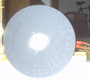
This was the first Nipkow disk I made and it is 20cm in diameter. You can see the spiral of holes, which are by far too big. The additional inner circle of holes can be used to measure the speed and estabishing an automatic synchronisation. This part was not used at this point. You can see the small DC-Motor driving the disk, all parts were salvaged from an old VCR.
However, in the meatime I made two other disks, 30cm in diameter, which increased the picture size to almost 1,5x3cm ( wow ;-). Viewed through a magnifying lens the picture can be streched to almost twice the sice, but at the expense of image brightness, which isn't the best in mechanical systems anyway.

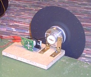
I know, it took quite some time and it is still not finished.
But after all it is working. The image is very small and dim and hard to capture, and I still have no real encasing for the device, though I doubt I will ever build one. Currently everything is mounted on some wooden board and supported on a heavy HV insulator serving as a stand, not too tidy but you can observe everyting very well.
The left circuit board carries the power supply and the video / sync sepserator unit, the right one the motor drive circuit. The syncronisation could work better, but it is hard to tell wheter the bad picture quality comes from sync problems, bad quality of the hand made cardboard disk or the limited abilities of the system itself. Circuit is closely oriented on the layout of Peter Smith.
However, it was German fellow tesla-coiler Eckhard Etzold who inspired me to finally build my own scanning disk set.
Jump to Eckhard Etzolds Homepage

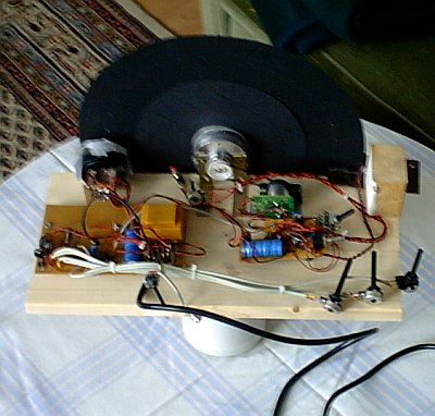
Yet some more changes. As you can guess I practically rebuilt the whole thing, at least an entirely new cabinet from beech laminated wood which was originally inteded to end up as a book shelf and with a thickness of 18mm is a bit on the large side.... build to resist ;-)
I just wantd to do something else than just a sheet of wood or a rectangular case. I can't repudiate a strong influence the casing of the original Baird Televisor had on my design, though the two cabinets look only remotely alike.
Here is the thing on my workbench under construction.

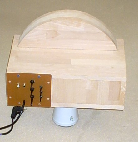
A view of the controlls located on the rear panel of the set. No knobs yet but controlls for volume, brightness, contrast, motor speed and sync level.
The half-round shaped extensions of the enclosure are made from 8mm beech wood I soaked in hot water and pressed into shape over a mould until dry.
This was my first try at bending wood and worked surprisingly well until now....
The base is a ceramic insulator from surplus HV switch gear.
Yes, this is perfectly neccessary... don't e-mail me about this.

The cabinet with both extensions and sanded with fine paper, ready for varnishing or staining.
My current idea includes staining the wood pretty dark and putting some layers of clear polyurethane varnish over it to provide a smooth shiny finish. At least this is the plan.
So stay tuned and don't miss when I terribly mess the paint job up ;-)

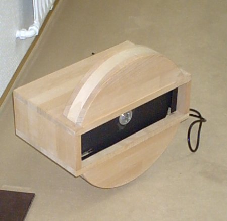
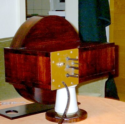
Varnishing job half finished. Did not mess it up as bad as previously indicated, but still a lot worse that it should be. Observed from a fair distance everythin looks great, but a close look reveals a very unevenly applied coat of clear varnish.
I am jus not particulary good with such tings, so I decided to leave it as it is for now, I can still rework it some other time. The pertinax board for the inputs and controlls now does no longer match the color of the cabinet and I am still looking for some nice knobs.

A view from the opposite site. The white aereas are remains of masking tape I haven't removed yet.

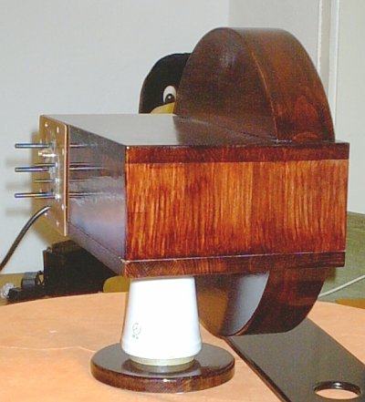
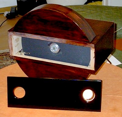
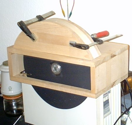
Front view with the front panel still seperate. Behind the left hole a small speaker will be located and behind the right one you can already see the magnifying lens where the picture will apprear.

Screenshot from the half finished device showing the NBTV logo.

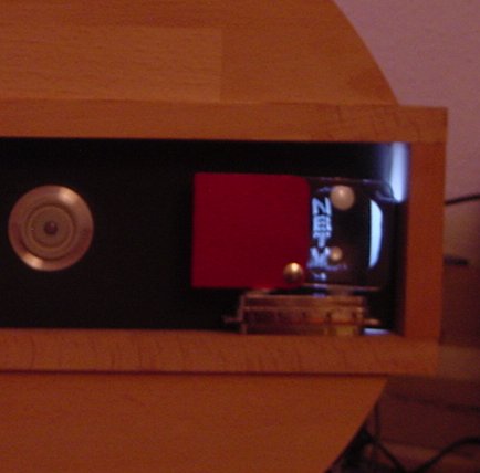
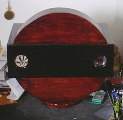
As you can see, I found time to make a front panel with two holes, one for the picture and the other for a speaker. I used a scrap piece of cloth as a speaker grill and I found, that the pattern on the cloth really gives the whole thing a somewhat qenuine appearance of anique apparatus. Although this is only the first impression and you can still clearly see its something homebuilt I am pretty satisfied with the project, now I will try to get the control circuits to run smoother and hopefully a better scanning disk. Currently you can see pictures pretty good but the image is not very stable and somewhat distorted. This is on the one hand caused by improper layout of the curcuits which are still the ones I lashed up when I started this project. On the other hand the cardboard disk is loosing shape which causes it to turn unevenly.


Home